How to Size a Wastewater Pump for Commercial or Municipal Applications: 7-Step Guide 2025
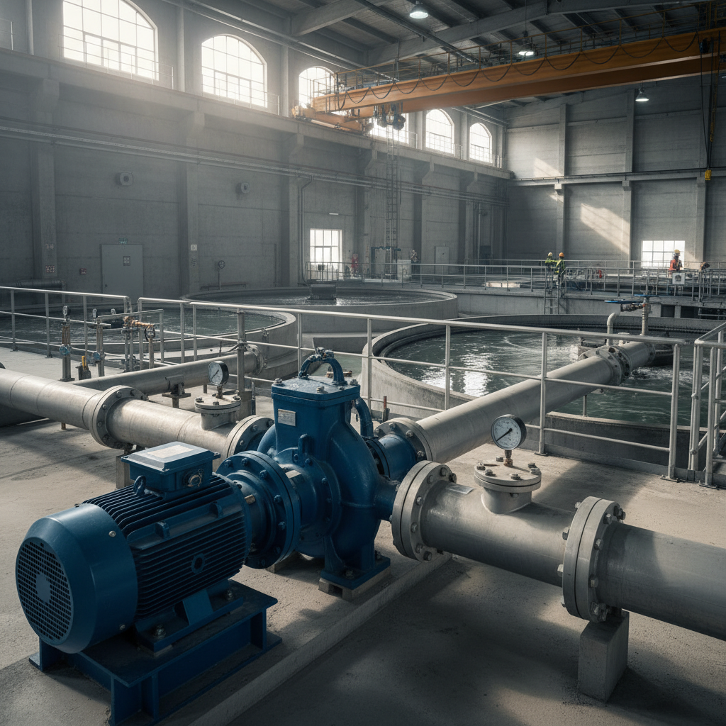
Properly sizing a wastewater pump for commercial or municipal applications ensures reliable sewage conveyance, prevents overflow events, and optimizes energy consumption over the pump’s life cycle. This step-by-step wastewater pump sizing procedure takes approximately 4-6 hours for experienced engineers and requires intermediate-level hydraulic design knowledge. By following this guide, you will determine the correct pump capacity, motor horsepower, and impeller type for sewage pump stations, lift stations, and wastewater treatment facilities.
Before You Begin: Prerequisites and Required Information

Skill Level: Intermediate (requires basic hydraulic engineering knowledge)
Time Required: 4-6 hours for complete pump sizing and specification
Information Needed:
- Design flow rate (GPM) for peak, average, and minimum flow conditions
- Wet well dimensions and elevation data for static head calculations
- Discharge piping layout, length, diameter, and material specifications
- Wastewater characteristics including solids content and temperature
- Local codes and EPA wastewater infrastructure requirements
- Pump manufacturer catalogs (Grundfos, Xylem, Sulzer, KSB, Flygt)
Tools Required:
- Hydraulic calculation software or spreadsheet for friction loss calculations
- Pump curve analysis software
- Hazen-Williams or Darcy-Weisbach friction factor tables
- Calculator for net positive suction head (NPSH) verification
Step 1: Determine Flow Requirements for Your Wastewater Pumping Station
Calculate the design flow for your commercial or municipal sewage system by analyzing historical flow data and projected peak demand. According to the Hydraulic Institute (2024), accurate flow rate determination prevents undersized pumps that cause overflow and oversized pumps that waste energy.
Calculate Peak, Average, and Minimum Flow Rates
For municipal wastewater pump station design, identify three critical flow values measured in gallons per minute (GPM). Peak flow typically occurs during morning hours (6-9 AM) and represents the maximum instantaneous flow rate your pump must handle. Average flow represents normal daily conditions, while minimum flow prevents pump cycling issues. Commercial building wastewater pump requirements vary: restaurants experience peak flow during meal service, hotels during morning checkout, and hospitals maintain relatively constant flow patterns.
Calculate flow variations using these multipliers for municipal applications: peak flow = 3.0-4.0 × average flow, minimum flow = 0.25-0.40 × average flow. For wastewater pump sizing for commercial buildings, conduct on-site flow measurement over 7-14 days to establish accurate baseline data.
Account for Future Capacity and Solids Handling Capability
Add 20-30% capacity to accommodate future growth in municipal collection systems, per EPA wastewater conveyance guidelines (2023). Determine solids passage size requirements: grinder pumps handle 1-inch solids, effluent pumps manage 0.5-inch particles, and submersible sewage pumps with non-clog impellers pass 3-inch spherical solids.
Step 2: Calculate Total Dynamic Head (TDH) for Your Sewage Pump Application
Total dynamic head represents the total resistance your wastewater pump must overcome, measured in feet. Accurate total head calculation combines static head, friction loss, velocity head, and pressure head components.
Determine Static Discharge Head and Elevation Differences
Measure the vertical distance from the wet well operating level to the discharge point elevation. Static discharge head equals the difference between the highest discharge elevation and the lowest liquid level in the pump station. For lift stations, this value typically ranges from 15-50 feet in municipal applications and 8-25 feet in commercial installations.
Calculate Friction Head Loss in Discharge Piping
Compute friction loss using the Hazen-Williams equation for calculating friction loss in wastewater pumping systems. For PVC and HDPE pipe (C=150), expect 2-4 feet of head loss per 100 feet at typical velocities of 4-8 feet per second. Include losses from fittings: 90-degree elbows add 2-5 feet each, check valves contribute 3-7 feet, and gate valves add 0.5-1.5 feet when fully open. Friction head increases with pipe length and decreases with larger discharge pipe size for wastewater pump systems.
Add Velocity Head and Pressure Requirements
Calculate velocity head using the formula V²/2g, where V represents fluid velocity in feet per second. At typical wastewater pumping velocities, velocity head contributes 0.5-2.5 feet to TDH. Add any required pressure head at the discharge point: force mains discharging to treatment plants may require 5-15 psi (11.5-34.6 feet) of additional pressure head.
Sum all components: TDH = static head + friction loss + velocity head + pressure head. For a typical municipal lift station, expect TDH values of 25-80 feet; commercial applications range from 15-45 feet.
Step 3: Select the Appropriate Pump Type and Impeller Configuration
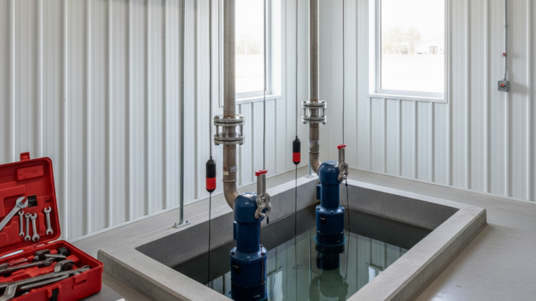
Choose between submersible pump installation (wet well mounted) and dry pit installation (separate pump room design) based on site constraints and wastewater pump installation requirements.
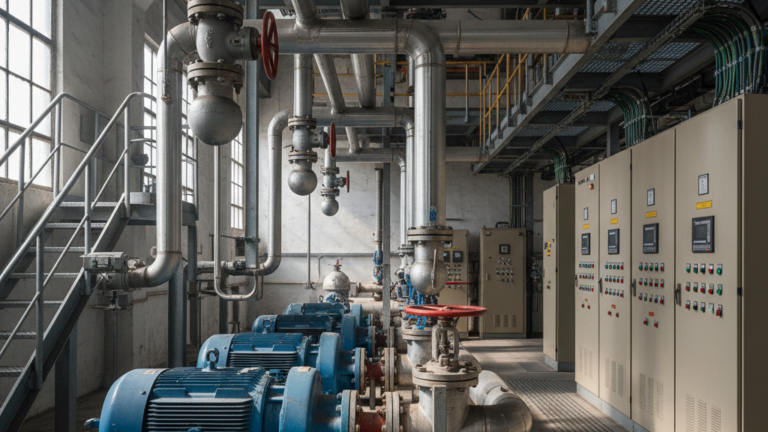
Compare Submersible vs. Dry Well Pump Configurations
Submersible wastewater pumps offer lower initial costs, simplified installation, and automatic cooling from surrounding liquid. These centrifugal pumps mount directly in the wet well and suit most municipal sewage lift stations and commercial sewage ejector pump sizing applications. Dry well configurations provide easier pump maintenance access but require dedicated pump room design with proper ventilation and drainage.
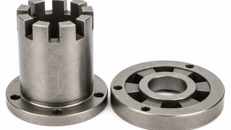
Select Impeller Type for Solids Content
Non-clog impellers handle municipal wastewater with 2-3 inch solids passage capability. Vortex impellers minimize clogging for stringy materials in commercial laundry wastewater pump sizing. Grinder pump selection for commercial applications requires cutting mechanisms that reduce solids to 0.25-0.5 inches. According to pump manufacturer specifications from Xylem (2024), selecting pump impeller for solids handling requires matching the largest expected solid size to impeller passage dimensions.
Step 4: Analyze Pump Curves and Match to System Head Curve
Plot the system curve and identify the pump operating point where it intersects the pump performance curve.
Plot Your System Resistance Curve
Create a system head curve by calculating TDH at various flow rates. Static head remains constant, while friction loss increases proportionally to flow² (or flow^1.85 for Hazen-Williams). Plot system resistance on a graph with flow (GPM) on the x-axis and head (feet) on the y-axis.
Identify Operating Point and Best Efficiency Point (BEP)
The duty point occurs where your system curve intersects the pump curve. According to the Hydraulic Institute, optimal pump reliability requires operating within 70-120% of the best efficiency point (BEP). Pumps operating significantly left or right of BEP experience reduced pump life cycle cost due to increased energy consumption, wear, and maintenance. For how to determine pump curve for sewage application, request detailed performance charts from Grundfos, KSB, Sulzer, or Flygt showing efficiency contours across the entire operating range.
Select a pump where the design flow intersects the pump curve at or near BEP. For variable flow applications, consider sizing variable speed wastewater pumps that maintain high pump efficiency rating across 40-100% of peak flow conditions.
Step 5: Verify Net Positive Suction Head (NPSH) Requirements
Ensure NPSH Available exceeds NPSH Required to prevent cavitation and pump damage. How to calculate NPSH for wastewater pumps involves analyzing suction conditions and atmospheric pressure.
Calculate NPSH Available (NPSHa)
NPSHa = atmospheric pressure head + static suction head – friction loss in suction piping – vapor pressure of liquid. At sea level, atmospheric pressure contributes 34 feet. For submersible installations with positive suction head (pump below liquid level), add the submergence depth. Subtract suction piping friction losses (typically 0.5-2 feet) and vapor pressure (approximately 0.8 feet for wastewater at 70°F).
Compare to Manufacturer’s NPSH Required
Pump curves specify NPSH Required (NPSHr) for cavitation-free operation. Maintain NPSHa at least 3-5 feet above NPSHr for reliable pump operations. For wet well design, ensure minimum liquid level provides adequate submergence: typically 2-4 feet above the pump inlet for municipal wastewater applications.
Step 6: Calculate Motor Horsepower and Confirm Energy Efficiency
Size the pump motor to handle design conditions plus a safety factor for calculating horsepower for commercial sewage pump applications.
Determine Required Brake Horsepower
Calculate hydraulic horsepower using the formula: HP = (Flow × TDH × Specific Gravity) ÷ 3960. For wastewater (specific gravity ≈ 1.0) pumping 500 GPM against 40 feet TDH: HP = (500 × 40 × 1.0) ÷ 3960 = 5.05 hydraulic horsepower. Account for pump efficiency (60-85% depending on pump size) and motor efficiency (85-95% for modern motors). Brake horsepower = hydraulic HP ÷ (pump efficiency × motor efficiency).
Add Safety Factor and Select Motor Size
Apply a 10-20% safety factor and select the next standard motor size. For the example above with 75% pump efficiency and 90% motor efficiency: brake HP = 5.05 ÷ (0.75 × 0.90) = 7.5 HP. With 15% safety factor, specify a 10 HP motor from standard sizes (5, 7.5, 10, 15, 20 HP).
Evaluate energy consumption over the expected 15-25 year pump life cycle to justify premium efficiency motors. Municipal wastewater pump energy efficiency improvements of 5-10% provide substantial operating cost savings. Resources from Pump Pros demonstrate that energy costs typically represent 40-60% of total life cycle costs for continuously operating wastewater pumps.
Step 7: Design Pump Control Strategy and Plan for Redundancy
Implement proper pump control and redundancy to ensure continuous wastewater treatment facility operations.
Specify Lead-Lag Control and Pump Alternation
Municipal pump station redundancy requirements mandate at least two pumps (duplex pumping system) sized for peak flow. Lead-lag control alternates which pump serves as primary, equalizing runtime and wear. How to size duplex sewage pump system: each pump should handle 60-100% of peak flow. For critical applications like wastewater pump sizing for hospitals, consider triplex configurations with three pumps each sized for 50-67% of peak capacity.
Configure Level Controls and Pump Duty Cycle
Set wet well level control switches to prevent excessive pump starts: maintain minimum 6-10 starts per hour for pump reliability. Calculate wet well storage volume to achieve proper duty cycle between minimum and maximum operating levels. How to determine wet well size for pump station: volume (gallons) = (GPM × 60) ÷ (starts per hour × 2). Include high-level alarm and emergency pumping backup systems for overflow prevention.
For variable speed pumping applications, program pump speed control to modulate output between 40-100% based on wet well level, maintaining operation near BEP across the flow range.
Troubleshooting Common Wastewater Pump Sizing Issues
If pump experiences frequent starts and stops: Increase wet well volume or adjust level switch differential. Verify minimum flow conditions don’t fall below pump’s stable operating range (typically 20-30% of BEP).
If pump cannot achieve rated flow or pressure: Recalculate friction loss and verify actual discharge pipe sizing matches design. Check for impeller wear reducing pump capacity calculation, or incorrect impeller diameter installation.
If pump cavitates or vibrates excessively: Verify NPSH available exceeds NPSH required by adequate margin. Check for air entrainment in wet well or vortexing at pump inlet. Increase submergence depth 1-2 feet.
If energy consumption exceeds projections: Confirm pump operates near best efficiency point. Operating at 50% or 150% of BEP significantly increases energy costs. Consider pump speed control or smaller pump for reduced flow applications.
If solids clog pump or impeller: Verify wastewater characteristics match pump specification. Upgrade to larger solids passage impeller or consider grinder pump for materials exceeding design parameters.
Next Steps: Installation, Testing, and Ongoing Maintenance
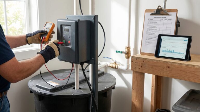
After completing wastewater pump sizing calculations and equipment selection, proceed with detailed commercial wastewater pump installation requirements following manufacturer guidelines and local codes. Conduct pump testing upon startup to verify actual performance matches pump performance chart predictions. Measure flow, discharge pressure, and power consumption at multiple operating points.
Establish preventive pump maintenance schedules: inspect pump materials for corrosion resistance and abrasion resistance quarterly, verify pump control strategy functions properly, and document operating hours for each pump in alternating pump operation systems. Monitor energy consumption trends to identify efficiency degradation indicating impeller wear or motor issues.
For facilities requiring submersible installation, develop confined space entry procedures for wet well access. Plan pump removal equipment and staging areas to facilitate future repairs. Maintain spare parts inventory including impellers, mechanical seals, and check valves based on manufacturer recommendations and municipal sewage pump station design guidelines.
Review pump selection criteria annually to verify continued suitability as flow patterns change due to development or process modifications. Update calculations if peak demand increases beyond original design flow or if wastewater treatment plant discharge requirements change affecting pressure head needs.